Thor here again! This week is my last week of working over the summer. The components we were waiting for came in, and Owen and I worked on assembling and testing them Tuesday. 

This is the front and back of our newest PCB design. We have 5 neopixels running across the middle of the board. On the back are some graphics and all of the names of the students who have contributed to the CATS CI.
We ordered 3 boards and the components to go with those boards. I began soldering the components by hand because the lab we usually use is closed for the summer and the professor who helps run it had to deal with orientation. Even the surface mount components were soldered by hand.

That speck on my first finger is an 0603 package 20pF capacitor. It is .06″ x .03″. I soldered two of these using a soldering iron to the board. A reflow oven is definitely preferred, but it was still a learning experience.

This beautiful component is a surface mount ATMEGA328P microcontroller. We are using this to drive our neopixels and the piezo buzzer on the board. The Pi will send serial bytes to the ATMEGA and it will respond by turning on the lights and buzzing when we need it to.
To program the ATMEGA chip, we have six holes in the PCB labeled “ISP1”. These are the ISP pins, just like on an Arduino. They are used for programming. Two pins are for power and ground, and the other 4 are MISO, MOSI, SCK, and RESET. This makes it easier for us to program the chip instead of using the Pi to program it. We can just plug the PCB into the Arduino that I was using to test the serial communication and program the chip while it is on the PCB.
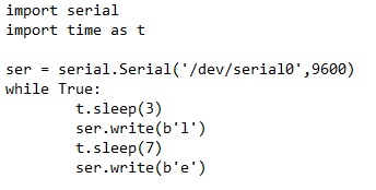
Owen helped me finish soldering and we began to test our device. I had code that I used when I tested the serial communication using a USB cable between a Pi and an Arduino, but this was a different application because, as I have recently learned, USB is different from TX and RX, or RS-232. We had to figure out how to modify my code to work for our devices. My code sent and read strings across the USB cable, but we had to change it because that was not working for RS-232. We read about making the string into byte arrays in the code, which is what string is converted into before it is sent. To make it even easier, we just decided to send one letter or byte at a time. We also had to change which ports were to be used for the communication in the code. Before, I was using the /dev/ttyACM0 port on the Pi, which is the USB port. We read that /dev/ttyAMA0 would work, but it wouldn’t work for us. It turns out that the Pi 3 is different, and ttyAMA0 is used for Bluetooth on the Pi 3. There is another port, /dev/serial0, which is the serial port we needed. There is also a /dev/ttyS0 which is the same thing, but the /dev/serial0 is preferred because the former is not as reliable from what we read. So if anyone is reading this and is dealing with a Pi 3 and needs help with a TX/RX connection, this could be the solution.

This is the new Pi code for the serial communication. We set up the communication with /dev/serial0 with a baud rate of 9600. Then we send the letter L after 3 seconds and E after 7 seconds.

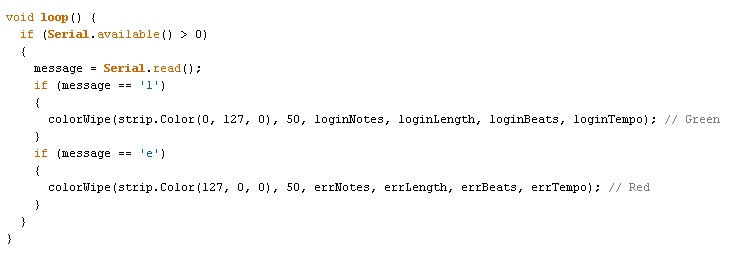
This is the new Arduino code for the ATMEGA chip. It checks the message sent to see if it is an L or an E. An L triggers the login light and sound which flashes green and plays the chest sound from the Legend of Zelda like I talked about before. An E triggers the error code which are red flashes and a buzzing. The colorwipe function originally made each light in the row flash on one at a time. It now flashes all the lights on when each note is played. Having all the lights come on helps to see the light from inside the box. There was an idea about make the cover for the box translucent because the lights are very bright.
Once we were able to get the ATMEGA chip working properly, we tested the EEPROM and the temperature sensor. Owen got the temperature sensor working so if the Pi is overheating it can alert someone. I was able to flash a .eep file onto the EEPROM. The shunt jumper we have on the board is connected to the EEPROM pads to allow for write protect. Putting the shunt on allows data to be written to and read from, and taking it off only allows reading from. When I first tried to flash data, it failed and we puzzled at it for a little. Then Owen remembered that the write protect was not on. We had not soldered the shunt jumper header on so Owen placed a wire from one pad to the other while I flashed the data and it worked just fine. The only thing that we didn’t get to was soldering the auxiliary connectors and the shunt jumper header on the board. Everything else worked from our tests, and we were so glad it did. Owen is ordering all the rest of the CI’s semester funds-worth of boards and components so that we can begin to assemble a lot more of them. When that time comes, we will definitely need to use the reflow ovens.
This summer has been very helpful for me. When I first joined this CI in the spring, our supervisor met with us to ask us about our goals for the CI. I said that I wished to learn more about how electronics work outside of class and how to program in the different languages that CATS uses. I learned about the electronics side for sure this past semester and a little about programming. I thought it was awesome and weird that I was able to program an actual device instead of making a program in class that prints “Hello world” to the screen. Over the summer I was working with an Arduino and had to learn about Arduino code, which is somewhere between C and C++. The Pi code for the serial was also in python, so I learned a little about that as well. I can’t say that I can start and finish a program in those languages by myself, but I can somewhat tell you what they do. I enjoyed working with the team in the spring and I have enjoyed working with Owen over the summer. We high-fived many times on Tuesday as everything started working, and I am so glad to be able to say that it works. Now our goal is to get the device onto machines and possibly implementing a Particle Photon instead of a Pi, but that is an idea for a later time.
This is Thor signing off!
