
It’s Thor again!
Last time I posted, I had edited our PCB to include an ATMEGA chip and a new ethernet port for an easier connection to the keypad. My idea of how big the ethernet cable is compared to the board was off, so the design was not good.
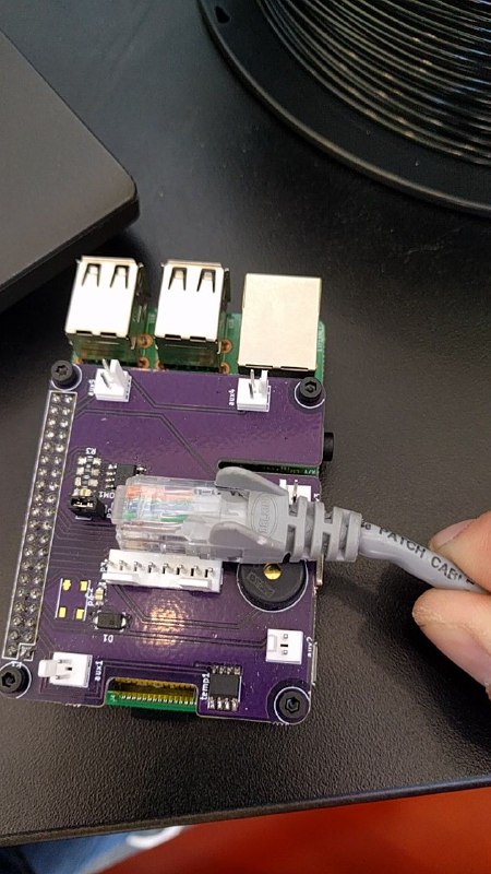
I had the ethernet port facing down the PCB (toward the right in the picture). This would have caused a problem with the cable and the piezo buzzer, so Owen redesigned the PCB. 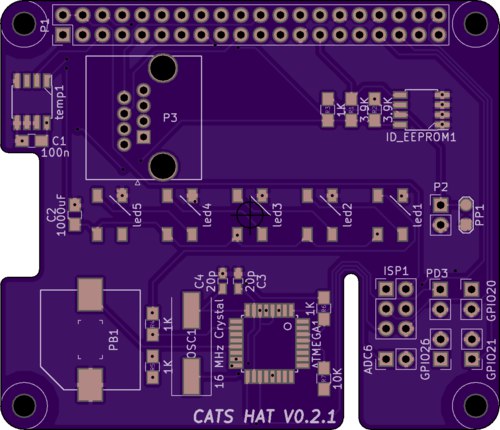
This is the picture from OSH Park showing what the new PCB would look like after manufacturing. The ethernet port is now turned to the right to not interfere with any components and there are 5 neopixels in a row in the middle of the board. The code to implement the strip is just a simple upgrade to the code for the one light that is on the board now. In the bottom left corner is the piezo buzzer. We are switching to a surface mount buzzer. In the bottom right corner are a few holes labeled “ISP1”. These will be used to program the ATMEGA chip on the board to avoid any problems programming it using the Pi.
I now have 11 days left of employment on the CATS device for the summer. Hopefully we can get the PCBs in and then it will be crunch time when I start soldering and assembling.
Until next time!