Summer 2017 Week 4

Thor here again! This week is my last week of working over the summer. The components we were waiting for came in, and Owen and I worked on assembling and testing them Tuesday. 016

017

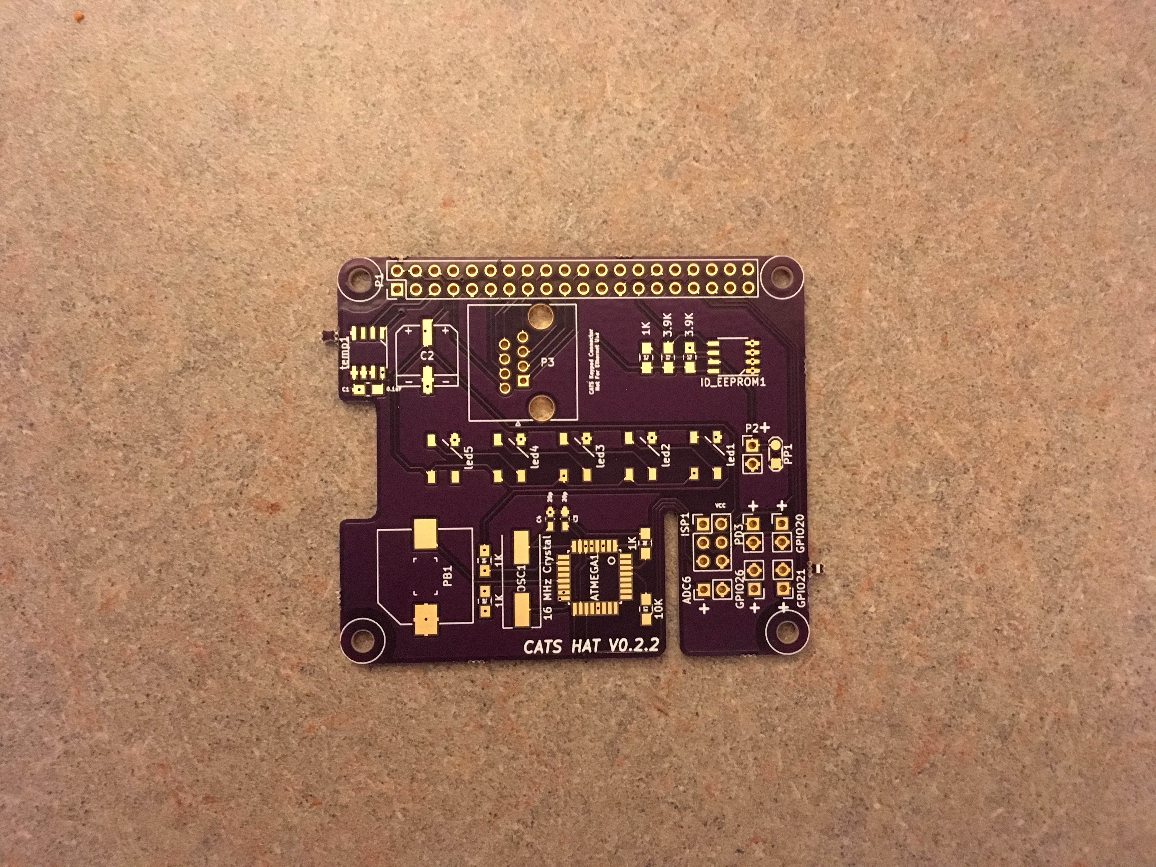
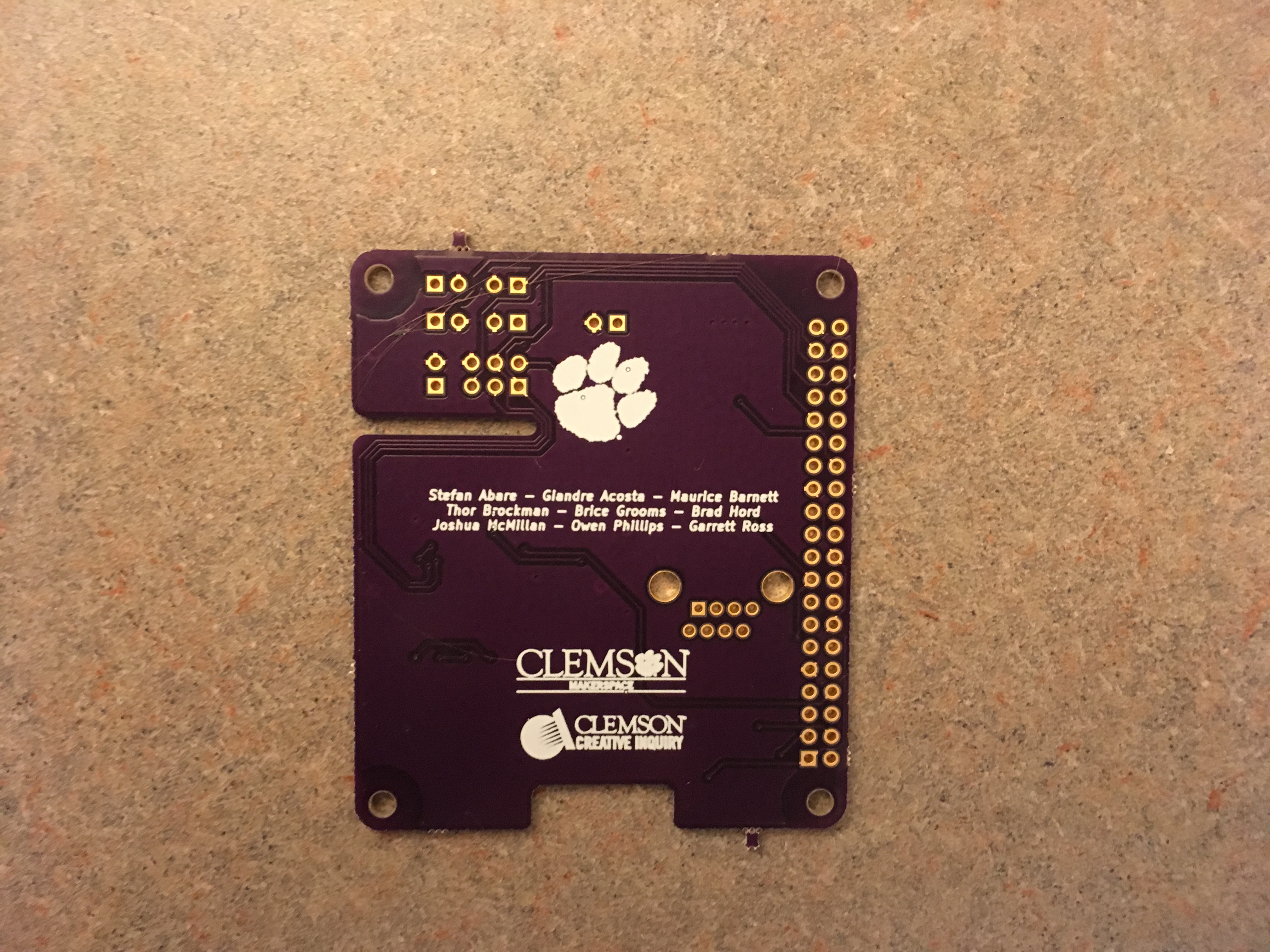
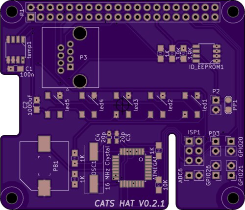
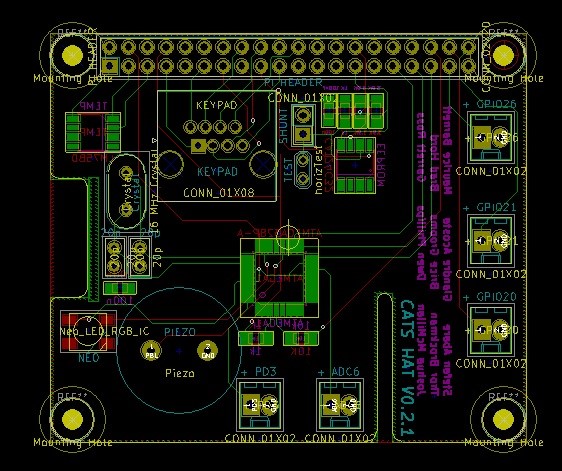
This is the front and back of our newest PCB design. We have 5 neopixels running across the middle of the board. On the back are some graphics and all of the names of the students who have contributed to the CATS CI.

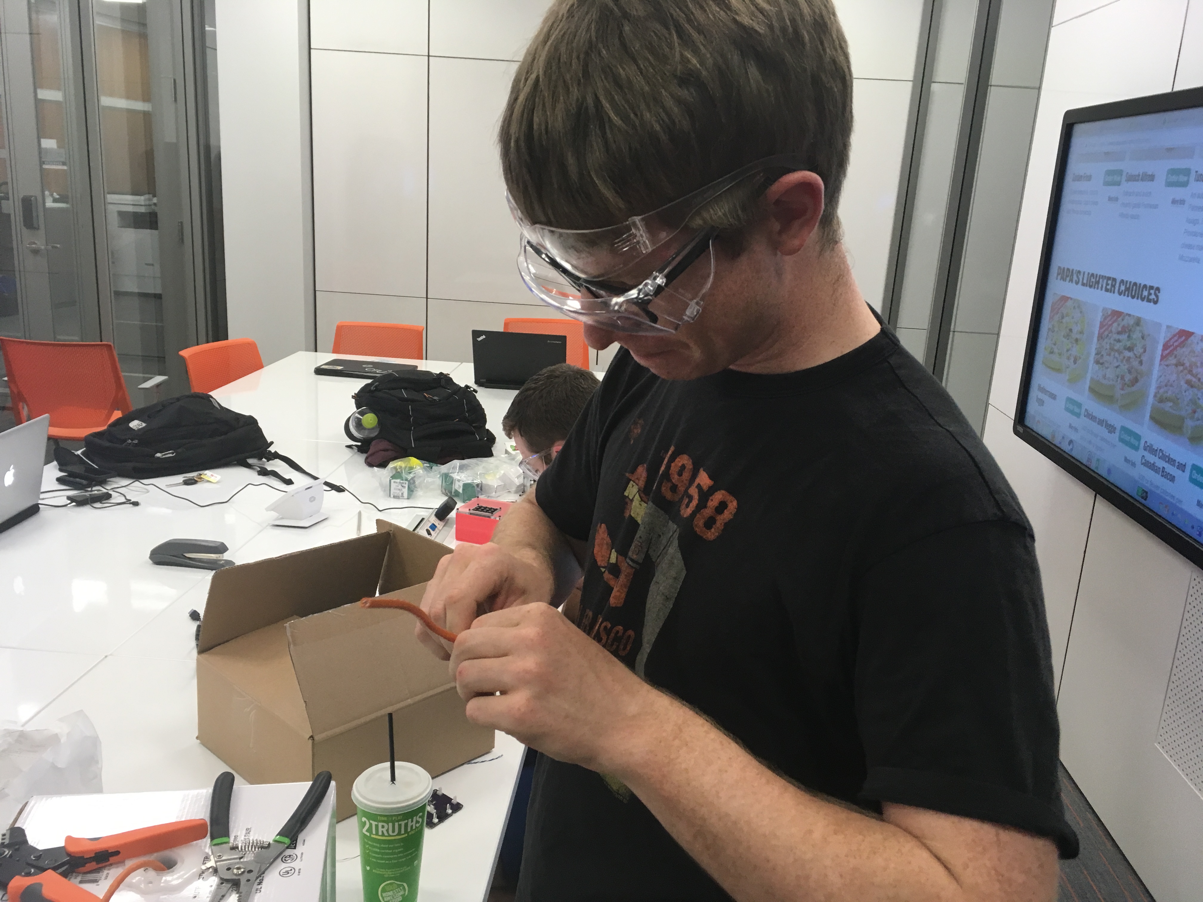
We ordered 3 boards and the components to go with those boards. I began soldering the components by hand because the lab we usually use is closed for the summer and the professor who helps run it had to deal with orientation. Even the surface mount components were soldered by hand.

018

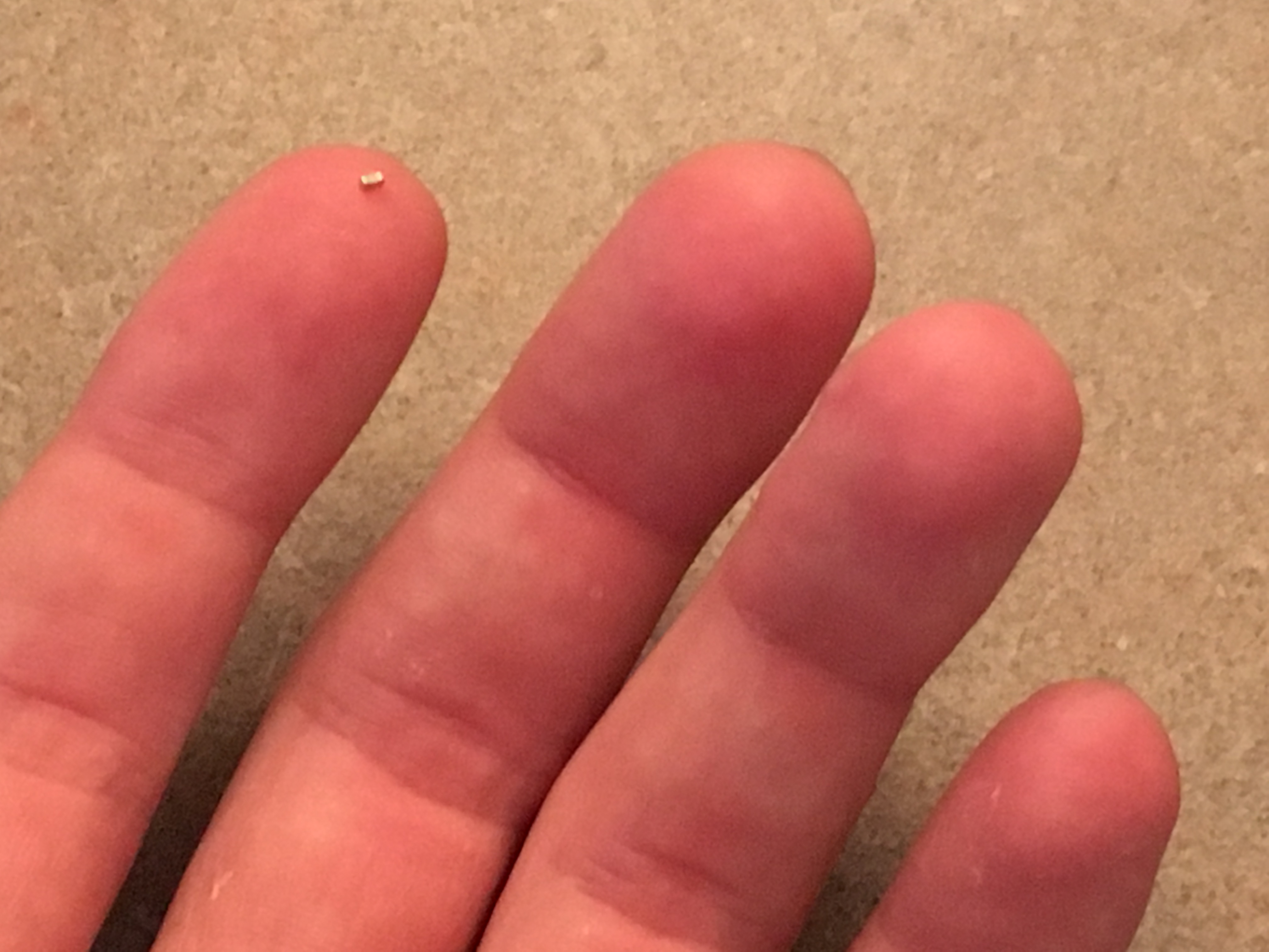
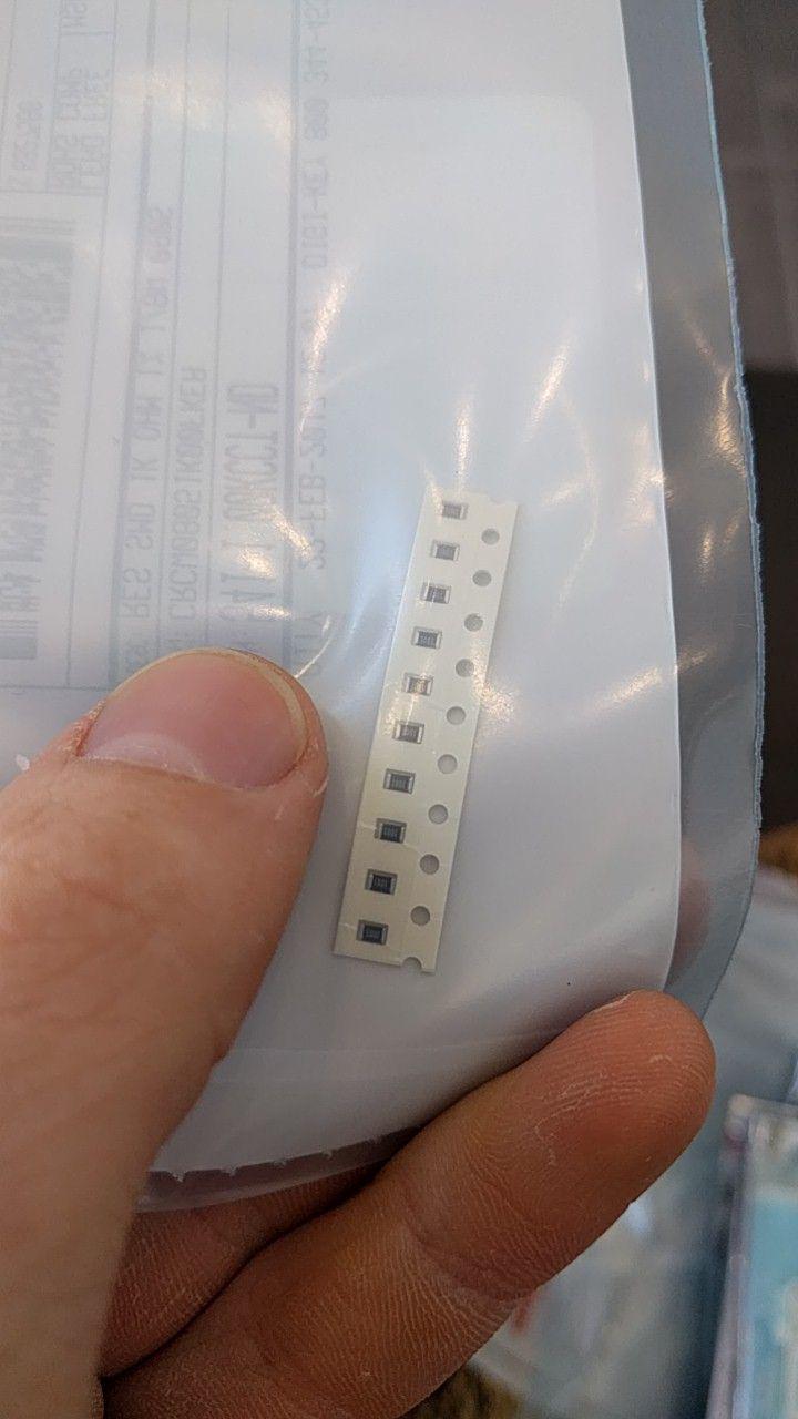
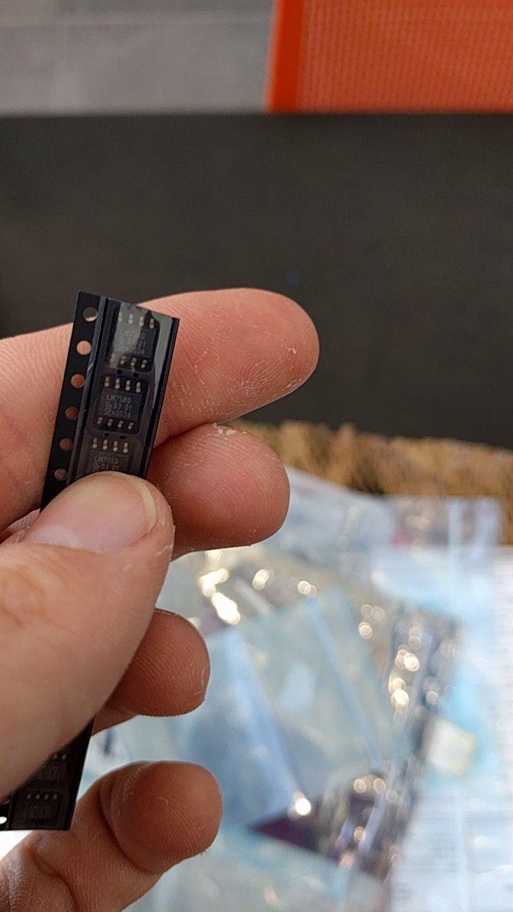
That speck on my first finger is an 0603 package 20pF capacitor. It is .06″ x .03″. I soldered two of these using a soldering iron to the board. A reflow oven is definitely preferred, but it was still a learning experience.

021

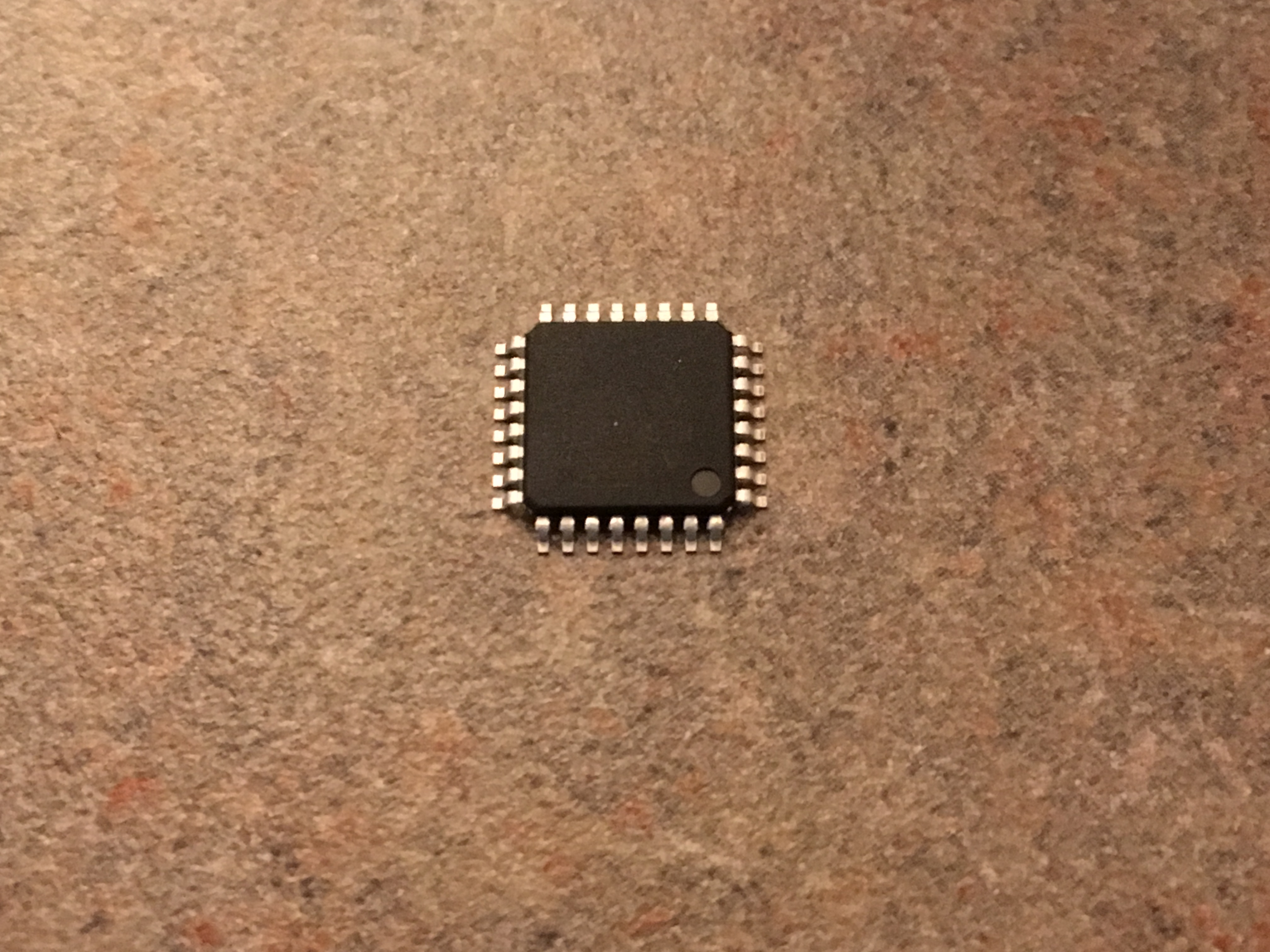
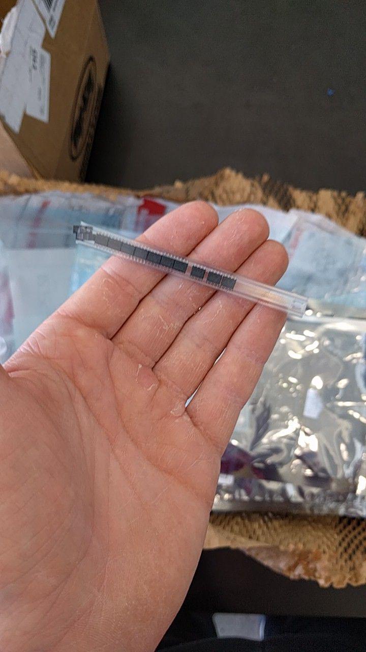
This beautiful component is a surface mount ATMEGA328P microcontroller. We are using this to drive our neopixels and the piezo buzzer on the board. The Pi will send serial bytes to the ATMEGA and it will respond by turning on the lights and buzzing when we need it to.

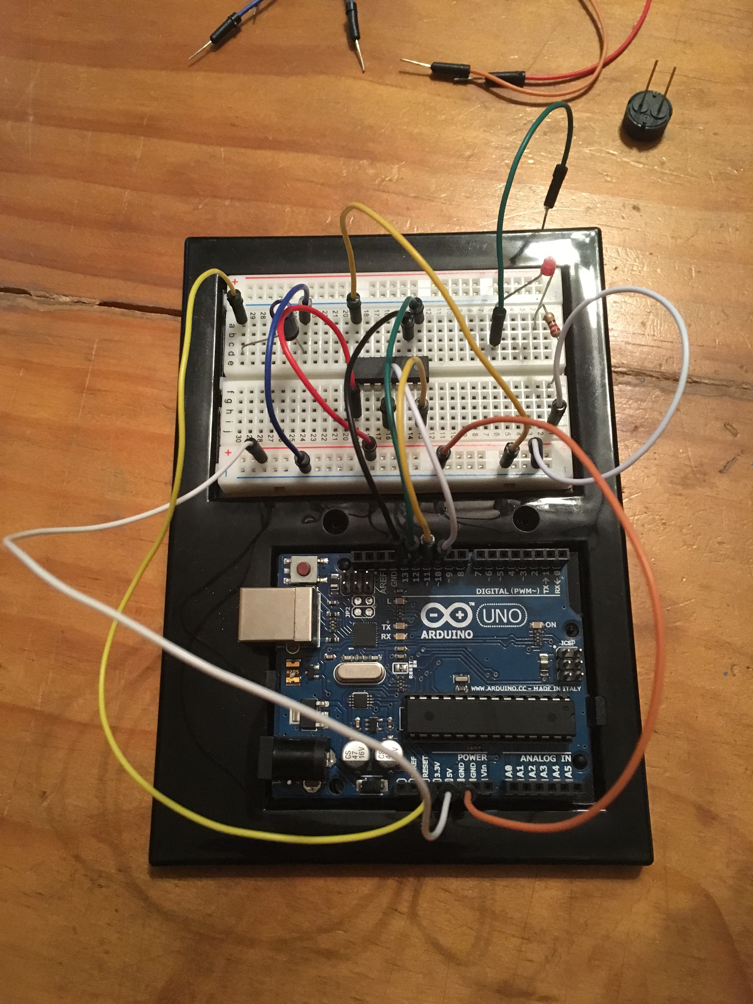
To program the ATMEGA chip, we have six holes in the PCB labeled “ISP1”. These are the ISP pins, just like on an Arduino. They are used for programming. Two pins are for power and ground, and the other 4 are MISO, MOSI, SCK, and RESET. This makes it easier for us to program the chip instead of using the Pi to program it. We can just plug the PCB into the Arduino that I was using to test the serial communication and program the chip while it is on the PCB.

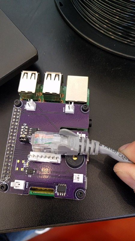
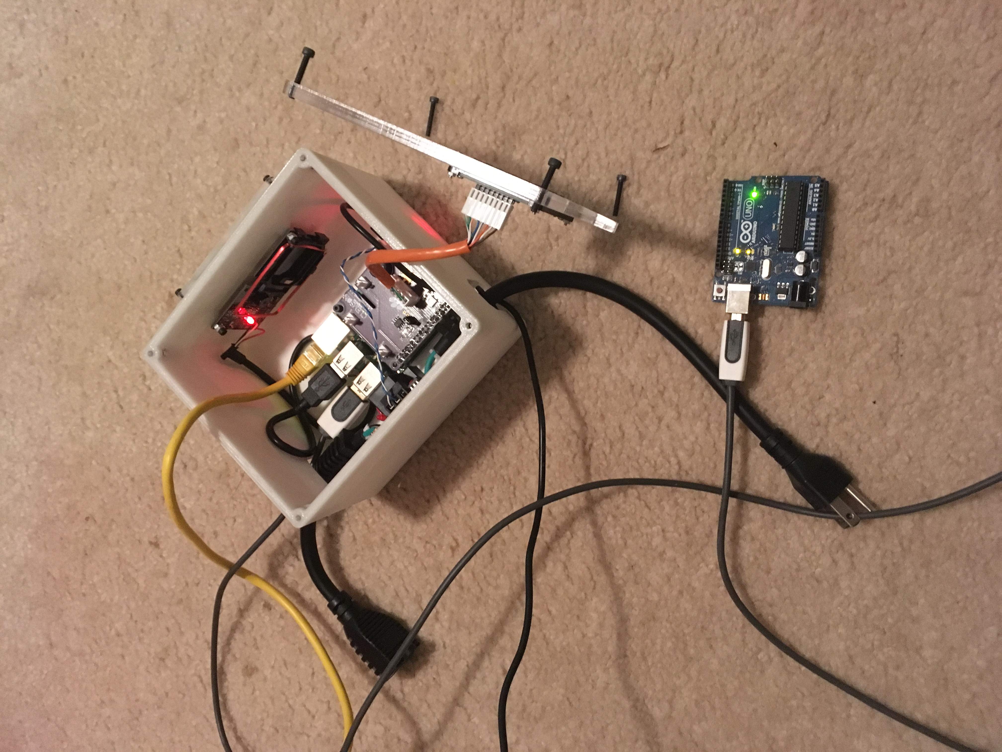
Owen helped me finish soldering and we began to test our device. I had code that I used when I tested the serial communication using a USB cable between a Pi and an Arduino, but this was a different application because, as I have recently learned, USB is different from TX and RX, or RS-232. We had to figure out how to modify my code to work for our devices. My code sent and read strings across the USB cable, but we had to change it because that was not working for RS-232. We read about making the string into byte arrays in the code, which is what string is converted into before it is sent. To make it even easier, we just decided to send one letter or byte at a time. We also had to change which ports were to be used for the communication in the code. Before, I was using the /dev/ttyACM0 port on the Pi, which is the USB port. We read that /dev/ttyAMA0 would work, but it wouldn’t work for us. It turns out that the Pi 3 is different, and ttyAMA0 is used for Bluetooth on the Pi 3. There is another port, /dev/serial0, which is the serial port we needed. There is also a /dev/ttyS0 which is the same thing, but the /dev/serial0 is preferred because the former is not as reliable from what we read. So if anyone is reading this and is dealing with a Pi 3 and needs help with a TX/RX connection, this could be the solution.

RPi Serial Code

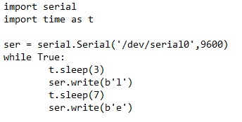
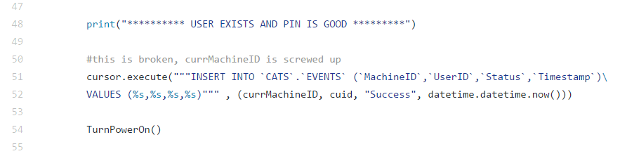
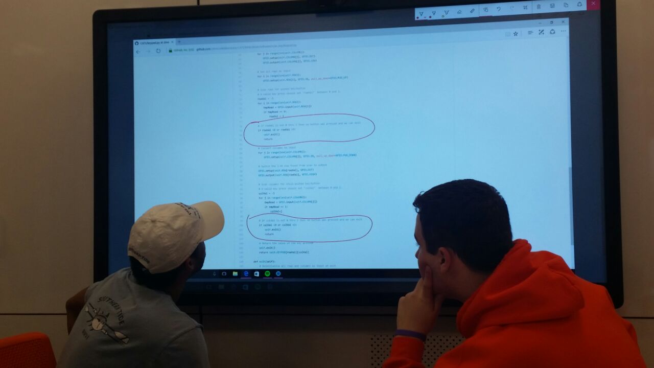
This is the new Pi code for the serial communication. We set up the communication with /dev/serial0 with a baud rate of 9600. Then we send the letter L after 3 seconds and E after 7 seconds.

Arduino Code

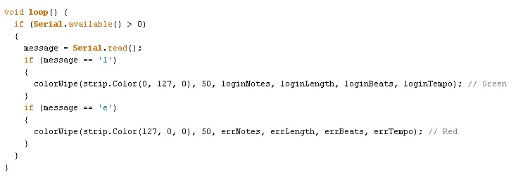
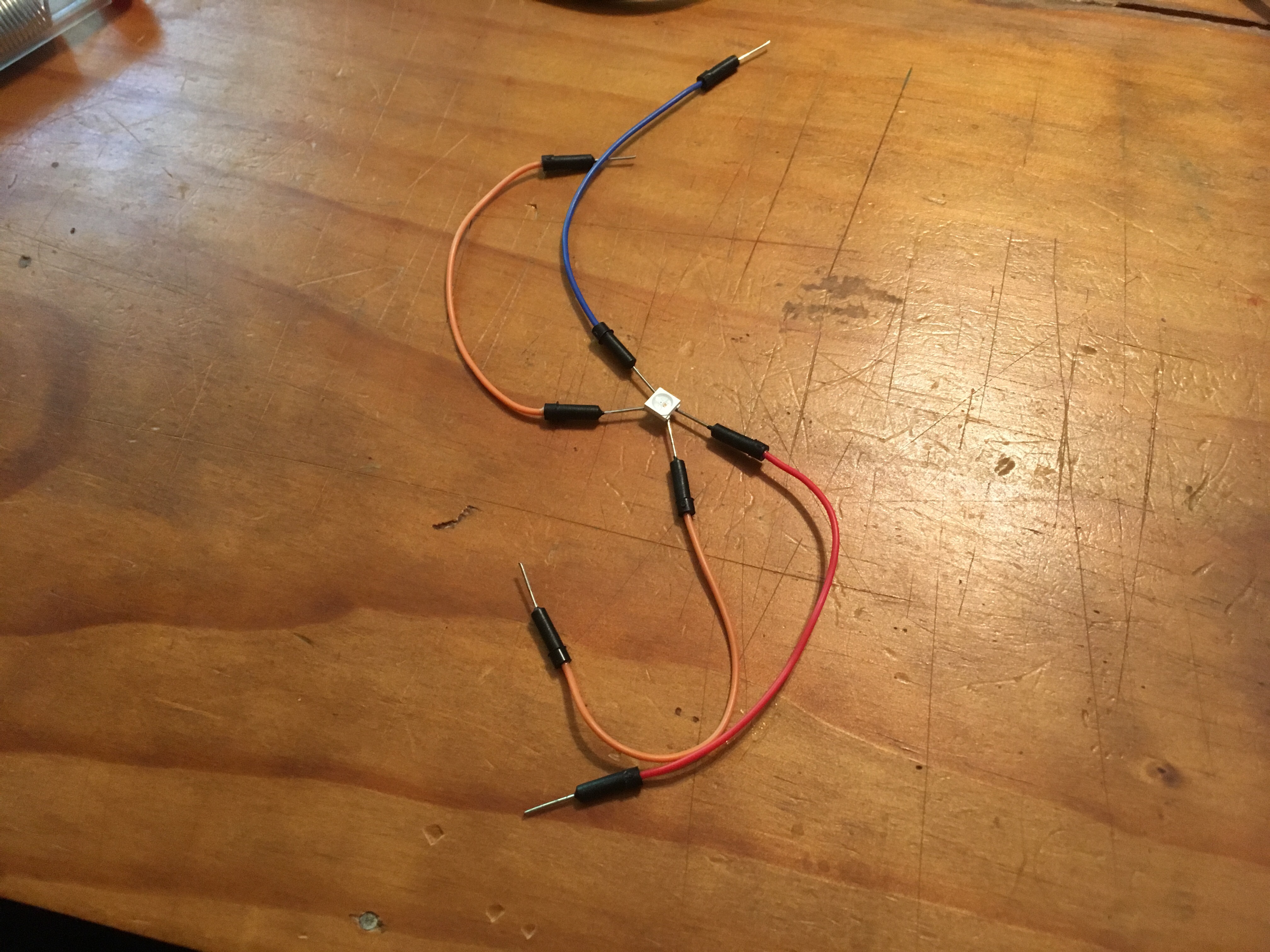
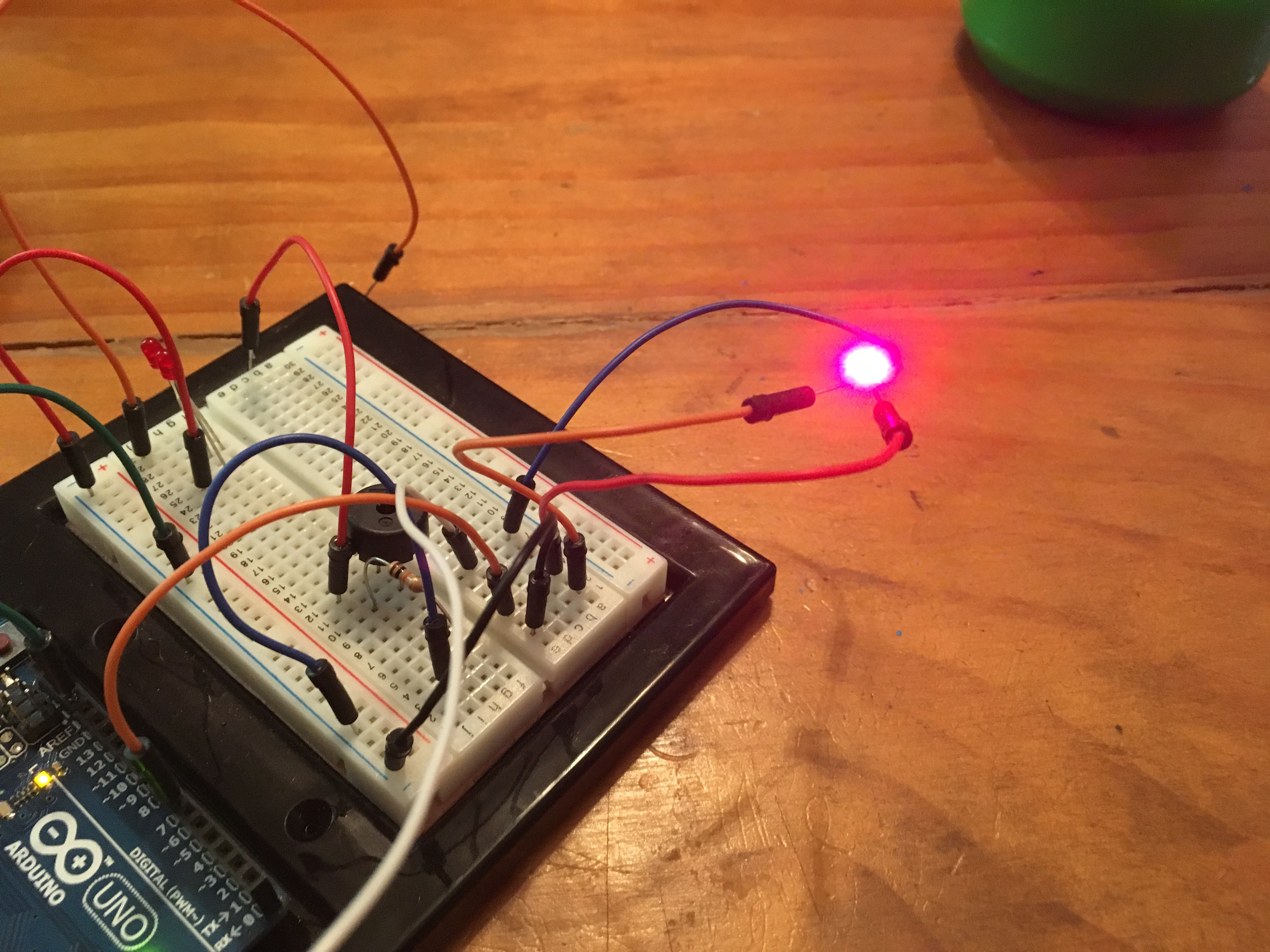
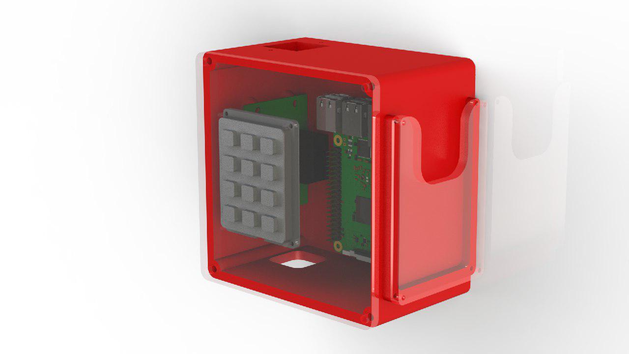
This is the new Arduino code for the ATMEGA chip. It checks the message sent to see if it is an L or an E. An L triggers the login light and sound which flashes green and plays the chest sound from the Legend of Zelda like I talked about before. An E triggers the error code which are red flashes and a buzzing. The colorwipe function originally made each light in the row flash on one at a time. It now flashes all the lights on when each note is played. Having all the lights come on helps to see the light from inside the box. There was an idea about make the cover for the box translucent because the lights are very bright.

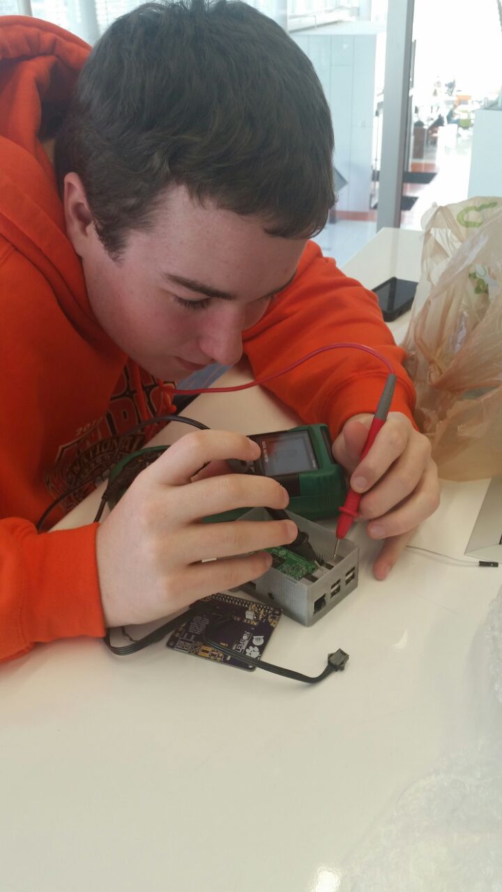
Once we were able to get the ATMEGA chip working properly, we tested the EEPROM and the temperature sensor. Owen got the temperature sensor working so if the Pi is overheating it can alert someone. I was able to flash a .eep file onto the EEPROM. The shunt jumper we have on the board is connected to the EEPROM pads to allow for write protect. Putting the shunt on allows data to be written to and read from, and taking it off only allows reading from. When I first tried to flash data, it failed and we puzzled at it for a little. Then Owen remembered that the write protect was not on. We had not soldered the shunt jumper header on so Owen placed a wire from one pad to the other while I flashed the data and it worked just fine. The only thing that we didn’t get to was soldering the auxiliary connectors and the shunt jumper header on the board. Everything else worked from our tests, and we were so glad it did. Owen is ordering all the rest of the CI’s semester funds-worth of boards and components so that we can begin to assemble a lot more of them. When that time comes, we will definitely need to use the reflow ovens.

This summer has been very helpful for me. When I first joined this CI in the spring, our supervisor met with us to ask us about our goals for the CI. I said that I wished to learn more about how electronics work outside of class and how to program in the different languages that CATS uses. I learned about the electronics side for sure this past semester and a little about programming. I thought it was awesome and weird that I was able to program an actual device instead of making a program in class that prints “Hello world” to the screen. Over the summer I was working with an Arduino and had to learn about Arduino code, which is somewhere between C and C++. The Pi code for the serial was also in python, so I learned a little about that as well. I can’t say that I can start and finish a program in those languages by myself, but I can somewhat tell you what they do. I enjoyed working with the team in the spring and I have enjoyed working with Owen over the summer. We high-fived many times on Tuesday as everything started working, and I am so glad to be able to say that it works. Now our goal is to get the device onto machines and possibly implementing a Particle Photon instead of a Pi, but that is an idea for a later time.

This is Thor signing off!

Summer 2017 Week 3

It’s Thor again!

Last time I posted, I had edited our PCB to include an ATMEGA chip and a new ethernet port for an easier connection to the keypad. My idea of how big the ethernet cable is compared to the board was off, so the design was not good.

Ethernet too big

I had the ethernet port facing down the PCB (toward the right in the picture). This would have caused a problem with the cable and the piezo buzzer, so Owen redesigned the PCB. Owen's redesigned PCB

This is the picture from OSH Park showing what the new PCB would look like after manufacturing. The ethernet port is now turned to the right to not interfere with any components and there are 5 neopixels in a row in the middle of the board. The code to implement the strip is just a simple upgrade to the code for the one light that is on the board now. In the bottom left corner is the piezo buzzer. We are switching to a surface mount buzzer. In the bottom right corner are a few holes labeled “ISP1”. These will be used to program the ATMEGA chip on the board to avoid any problems programming it using the Pi.

I now have 11 days left of employment on the CATS device for the summer. Hopefully we can get the PCBs in and then it will be crunch time when I start soldering and assembling.

Until next time!

Summer 2017 Week 2

This is Thor again, back with some more summer news! Since the last post, it has been a little slow because of waiting for the order to arrive so I can assemble the new boards. Last week I was able to have the Arduino control the successful login sound and light. I have now coded an unsuccessful sound and light. All it does it beep and blink red, but the Arduino is able to read in a string sent serially by the Pi. If the Arduino reads in “login”, then the successful code runs and if it reads in “error”, the other code runs. This way, we can have different sounds and lights set up to execute at different times when certain actions occur. The Pi can sent string serially and then continue on with the code while the Arduino takes care of the light and sound. This will prevent interruptions in the Pi code so the keypad can function at a fast pace. On the new PCBs, we have the serial connection between the TX (transfer) and RX (receive) pins on the Pi and Arduino. They will have to be tested when we assemble them because I was only testing the connection over a USB cable. Only the RX from the Arduino and the TX from the Pi are going to be connected, so that the Pi can send strings to the Arduino. We do not need to send anything back to the Pi. The Arduino also runs on 5V logic while the Pi runs on 3.3V logic. The Arduino can handle and understand the 3.3V signals coming in from the Pi but vice versa would need a voltage divider. To simplify the hardware, we are not going to have the Pi receive anything back from the Arduino for now.

Once the shipment of parts arrives, we can assemble them and hopefully our devices work the way we intended so we can begin installing them on machines if time permits.

Until next time!

Summer 2017 Week 1

This is Thor here! I am working with the CATS device over the summer as a job and somewhat of an internship! When we left off during the spring semester, the device was able to scan in IDs and log people in who were in the system. We spent a couple of late nights working to assemble the devices for a “Maker Day” event where we and other creative inquiries showed our projects to curious students.

IMG_5270

This is Owen with two safety goggles on helping me strip ethernet wire. We used this wire because it is eight wires wrapped together and we needed eight wires for our keypad. We have a couple hundred feet of it in a box so I think we are good for the remainder of the CATS CI. We decided to crimp our own wires and put them into housings to connect to our wire-to-board connectors on the PCB. The pre-crimped wires we found were individual and would have to be wrapped to stay together, and we could not find ribbon cables that would work. Crimping wires is very difficult starting out, but Brice, Maurice, and myself were able to crimp the wires we needed.

The Maker Day event was really fun because not only was our device working for others to see, but we also got to see other inspiring projects. 3-D printed stands were made for our devices to give them a more professional look for the event, and they looked really good!

DSC_1190

This is Giandre demonstrating the devices. We could scan our IDs and the relay light came on to show that power was running through the relay.

Giandre_3

Here is a close up of the device. We had three boxes with different designs on them. The purple has a Clemson logo, the brown has cats (CATS) all over it, and there was one more with a honeycomb pattern on it, which had a glow-in-the-dark trim around the front edge.

That event was close to the time that exams were coming up, so that was the last time we really worked on it for the semester. I was hired for the summer and have continued to work on the CATS device since around mid May.

There were a few problems that we had during the spring semester. We were not able to implement the cheaper card scanner that we were hoping for, and there was a problem with driving our Neopixel LED, piezo buzzer, and keypad. The keypad entry was being interrupted by the blinking light and beeping from the buzzer. We decided to add a second microcontroller to help with driving these components. I have been working on implementing the second microcontroller since I started working for the summer.

IMG_5351

This is an Arduino Uno connected to a breadboard with an ATTiny microcontroller. The Arduino’s microcontroller (an ATMega328P) has multiple PWM pins which are digital pins acting as analog signals which can drive the Neopixel and the piezo buzzer. The Raspberry Pi only had one PWM pin so it was used for the Neopixel and the piezo buzzer and keypad were connected to regular digital pins. With multiple PWM pins, the ATMega328P would help control the light and sound. We would just need to control that microcontroller through serial communication with the Pi. I was testing serial communication between the Arduino Uno and the ATTiny in the picture above.

IMG_5340

IMG_5343

This is my precious. Owen named it “Frankenpixel”. Because the neopixel is a surface mount device, I could not test it on a breadboard by itself. So, I soldered some jumper wires to the pads and have been using them to stick into the breadboard. It works how I need it to, and I can play the end part of the treasure chest sound in the Legend of Zelda games while a green light blinks to indicate a successful login.

IMG_5359

I decided to stop testing the serial communication from the Arduino to the ATTiny because I needed to edit the PCB and get it on GitHub. I plugged the Arduino to the Pi through USB and was able to have the Pi send the serial string “login” to the Arduino after 5 seconds. The Arduino would read that string in and if it read in “login”, it would play the sound and blink the green light. It worked beautifully. I then edited the PCB to include an ATMega328P-AUR chip which is the surface mount version of the Arduino Uno’s microcontroller.

PCB (2)

This is the new PCB as of right now. The ATMega chip is in the middle and I changed the keypad header to an ethernet port so it is easier to plug into the board. Owen is reviewing it for me and hopefully it works so that we can order them and assemble them quickly. That is about all that has happened since the last post, and I will continue to post throughout the summer about how this job is coming along.

Until next time!


Week 6-7


Hey guys. This is Joshua McMillan, and this is your week 6-7 blog post.

So, the adventures of creating a fully functioning machine access tracking system continues. We have faced some challenges but we faced them with a sense of determination that knows no bounds. The hardware team produced the final design of the electrical enclosure in solid works. photo_2017-03-13_09-38-49

One of the biggest challenges for the hardware time was vanquishing the forces of darkness that seemed to be halting our progress on the 3-D printing of our electrical enclosure. The fruits of our labor seemed to fall short of glory.

why

^This was our second attempt at printing the enclosure.  However, on the third attempt,  Stefan was able to overcome our problems by printing the enclosure at his place.

Enclosure

TADA! This enclosure is looking good! The front and side pieces were laser-cut out, and the enclosure is now only missing the electronic parts.

In other news, many of the parts that were required for us to finish our machine access tracking system finally came in. These parts included a 250 foot cat-6, 1kohm resistors, an Eeprom and temperature sensors.

250 ft cat 6a1kohm resistorEeprom   Temp sensors

The software team has developed an optional two-factor Authentication system. However, there are a few lines of code are giving us trouble. The lines 50-52 are not executing correctly.

software

The SQL Machine Table was designed for the two factor Authentication system. If the machine Int is 2, the Pin and ID is required. If it is 1, the PIN is mandatory. If it is 0, then no keypad is required, just the ID.

USER SQL

ID | PIN | OPT

1 | 1111 | 1

2 | 2121 | 0

3 | 4123 | 1

4 | 6134 | 0

Week 5 of 2017

This weeks blog will feature a dual post from Stefan and Brad:

It has been a busy last week for all the students on the team as we have seen a wave of tests sweep campus for all majors. To catch everybody back up with what has happened with the team I’ve included a short synopsis below:

There was some weird things happening to the team after they were terrorized by a monster named Grendel the day or so after Brice had posted his blog update. Owen managed to rip off Grendel’s arm and then defeats Grendel’s mother with some cool armor he had 3D Printed.

Owen became king of the CI Members, and found his project terrorized by an Exploding Capacitor, some of his progress had been stolen from his box containing the CATS project. He attacks the Exploding Capacitor with the help of his hardware team, but they do not succeed. Owen decides to follow the Exploding Capacitor to its lair at The Watt Family Innovation Center, but only his young Swedish relative Wiglaf, whose name means “remnant of valor”, dares to join him. Owen finally slays the Exploding Capacitor with the help of the hardware team, and Wiglaf, but is mortally wounded in the struggle. He is cremated and a burial mound by the sea is erected in his honor.

The hardware team finished their work with the PiHat and with the Enclosure for the system. These are currently on order and will be received and printed by next week’s blog post. Brad made a pretty sweet website.

-Stefan

803120381_12372_13638293004437926160

“The Exploding Capacitor: An Old English Epic Poem”

803115219_12465_8585157050172675524

Owen, seen smiling next to the defeated Exploding Capacitor

804206952_14391_15601324075360210447

Software team, debating ‘if’ statements

803734908_61501_10244787990066529410

Young Morris learns to solder

Oh.. and the website stuff

1

Home Page

Login

Login

LoginConfirm

Login

machinecontrolpanel

Machine Control Panel

AddMachine

Add Machine Form

UsersControlPanel

User Control Panel

AddUser

Add User Form

logoutconfirm

Logout Confirmation

Unfinished Features:

  • Events Table
  • Export Events, User, and Machine tables to Excel
  • Visual Graphs on Events, User, and Machine metrics
  • Machine State Toggle Functionality
  • Authorization Controls

Sources:

Lore – https://en.wikipedia.org/wiki/Beowulf#Third_battle:_The_Dragon

Bootstrap/HTML/CSS Coding – https://www.w3schools.com/

Data Tables – https://datatables.net/examples/server_side/select_rows.html

Data Tables With in Table Controls- https://editor.datatables.net/examples/simple/inTableControls.html

Debugging/Error Handling – http://www.tutorialrepublic.com/php-tutorial/php-error-handling.php

Forms – http://bootsnipp.com/forms


Icons – http://fontawesome.io/

Password Hashing – http://php.net/manual/en/function.password-hash.php

Toggle Switch – http://www.bootstraptoggle.com/

-Brad


Week 4 of 2017

Although this week wasn’t busy for the CATS team, some big stuff happened.  The hardware team’s work began to come together this week.

Thanks to Thor’s hard work, the brand new PCB design was finalized!  We will order the new PCBs as soon as a new Mr. Bill of Materials is completed so that we can also order the new components we’ve picked out.  In addition, the funding for our project was finally approved.  This means that we can finally order a new RFID scanner for Maurice to play around with implementing.  The new housing design was completed ahead of schedule by Stefan and Josh.  We made an attempt to 3D print the housing but unfortunately our print failed after only a few hours.

The hardware team should be pretty busy over the next few weeks.  Once the new PCBs arrive we will have to learn how to solder surface mount components and someone will be tasked with programming the EEPROM we implemented in order for our PCB to be called a PiHat.  If we can order the new RFID scanner we want, Maurice will be busy for the next week or two getting the driver software in order to make it work.  We will also be printing housings and laser cutting face-plates for our newest prototype.

Week 3 of 2017

Hello interwebs!

My name is Thor, and I am a new member of the CATS Creative Inquiry squad. I am majoring in Computer Engineering, and am part of the Hardware team for the CI. I met Owen last year, and he wouldn’t stop bugging me about joining his CI so I decided that it would be a great way to gain experience with circuits, which is a huge passion of mine. It’s been an honor meeting the rest of the team and I’ve enjoyed being a part of it for this short amount of time.

These past few weeks have mostly been a learning and research experience. I’ve had to learn how everything connects and what all the components on the Raspberry Pi and our PiHat do, so I have a better understanding of where the traces on our PCB should go. Another big thing I have had to learn is how to work KiCad. Working on it makes me realize that I am actually contributing to how the design will turn out, and that’s been an awesome feeling.

So far, I have helped with redesigning the footprints on the PiHat board. We are also changing the LED on the board to a Neopixel to add nicer color effects. I was in charge of researching this and a diode that could be used to supply the correct amount of voltage to power the Neopixel.

The Hardware team hasn’t had too much on its plate since the beginning of the semester, but Software team has definitely been busy. They are a good group of guys who have been working hard on this project. I can’t explain what they have been doing very well, but I know they are still working on getting the other card scanner to work with our cards, the requirements.txt file, and the audio features.

I got a chance to see the admin panel being worked on, and it is looking good right now. We are able to add admins to the database now, so that seems to be going very well.

I believe that covers most of what has been going on (and what I actually understand as of right now). I think this semester will be a challenge but it will definitely be worth it working on this team.

Until next time!

Week 2, 2017

Maurice here,

We’ve got lots of plans for this new semester of work.

Brad and company on the web interface team got a webpage up and almost running and ready for putting lots of great content into it. They plan to have a login page working very soon (in a few days).

Giandre and software team are making lots of plans to fixing some behind the scenes infrastructure to the computer. We’re doing this by squashing any bugs that pop up and creating things such as requirements.txt and config files. Giandre is also planning on implementing audio feedback. Not really any immediate goals for this, code upgrading is kind of a work in progress always.

Brice and the hardware team are working on stuff such as a secondary hat for the Pi, making a new sturdier housing, and collaborating with the software team on getting the cheaper scanner to work (which is a personal project of mine). Getting the cheaper scanner to work is important to me because it will shave off lots of cost for each unit. I can taste the solution to getting it to work, we’re just in the process of getting in touch with HID (the card and scanner manufacturer) with getting everything finalized. Hopefully we’ll have more insight into the solution in the next few days.

That’s all I can really think of for this week,
Go Tigers!

Week 1 of 2017

Hello my friends and welcome back to a New Year with new expectations about how the Clemson (Machinery) Access Tracking System (CATS) project will continue for the Spring of 2017 semester.

This year the creative inquiry team decided to take a new approach on how we wanted to separate the tasks for the project. We ended up creating three teams that consist of Hardware, Web Administration, and Software (Raspberry Pi Coding, SQL server components, and more…).

Over Christmas break of 2016, one of the members of the team decided to take a Raspberry Pi home to fix a problem or bug that the needed fixing. This one problem was having the Invalid PIN re-entered if the user had entered an incorrect PIN. Not only was this issue solved, but the member added a signal interrupt that lets the system lock the user out if they have not typed in something within a certain time or if the card is no longer being read, for now this timer is set at 7 seconds.

With that being said, there are a few goals that the three teams are going to tackle this semester.

Hardware

  • Redesign Housing
  • Solve Connectivity Issues
  • Improve User Interface and Feedback
  • Integrate Relay Into Design of PCB
  • Integrate Physical Safety Features such as Captive Ends for Power Supply

Software

  • Complete Unit Testing
  • Improve Quality of Code
  • Fix/Reduce Bugs Found
  • Implement the Software Development Life Cycle
    • This step will be put into effect when the team gets close to the finished product
  • Implement *Optional* Two-factor Authentication
  • Add Audio Effects

Web Administration

  • Home page with Administrator Login
  • Database Calling
  • Machine Control Panel
  • Data Metrics Panel

That is all for this week’s blog. Thank you for your time. Hope to see you all back soon.

‘We’re the CATS Team and we approve this message.’